Precision RF / Microwave Testing Services
Accurate characterization is paramount to the development of high performance RF / microwave / wireless devices and systems. Echoic provides precision measurement services using industry grade instrumentation coupled with a proficiency in testing and characterization methodologies.
We are experienced in configuring customized setups for measuring small signal S-parameters, large-signal power, noise figure and DC parameters. We are also familiar with industry-standard protocol for measuring linearity, noise, stability, mismatch, ESD, reliability and thermal behavior.
Additionally, we have pioneered the use of pulsed characterization for high power transistor devices
Echoic Engineering operates a full-service general-purpose RF and microwave lab with capabilities up to 26.5GHz. We are currently offering testing-as-a-service and can provide the right expertise for your RF testing needs.
We can help you:
- Identify the performance of unknown components (e.g. uncategorized SMTs)
- Verify the proper operation of procured parts
- Isolate parts which do not meet spec compliance (e.g. random sampling, extraction and testing of integrated components)
Testing services include:
- S-parameter characterization
- Large-signal CW and pulsed power characterization
- IV and dynamic IV characterization
How it works:
- Step 1: Contact us with your testing needs!
- Step 2: Send us the parts if you have them OR we can source it from the vendor
- Step 3: We will configure our test setup for the appropriate test
- Step 4: We will email the data and send that part back to you with a detailed report
- Step 5: Optionally, we can hold onto the part and perform additional testing at your request.
Small Signal testing (S-parameters)
Accurate characterization and spec-compliance are critical in evaluating components for use in your design. Small signal validation allows your to be sure that parts that you are sourcing from the manufacturer matches their datasheet. Echoic Engineering is capable of providing precision, de-embedded, calibrated S-parameters up to 26.5GHz. A wide variety of active and passive components can be tested.
Case 1: Mini-circuits LFCN-2500 Ceramic Wifi Low Pass Filter Surface Mount Chip
The S-parameters measured in our lab closely match those of the vendor provided data. We can see with confidence that this part is authentic and meets specs.

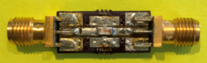
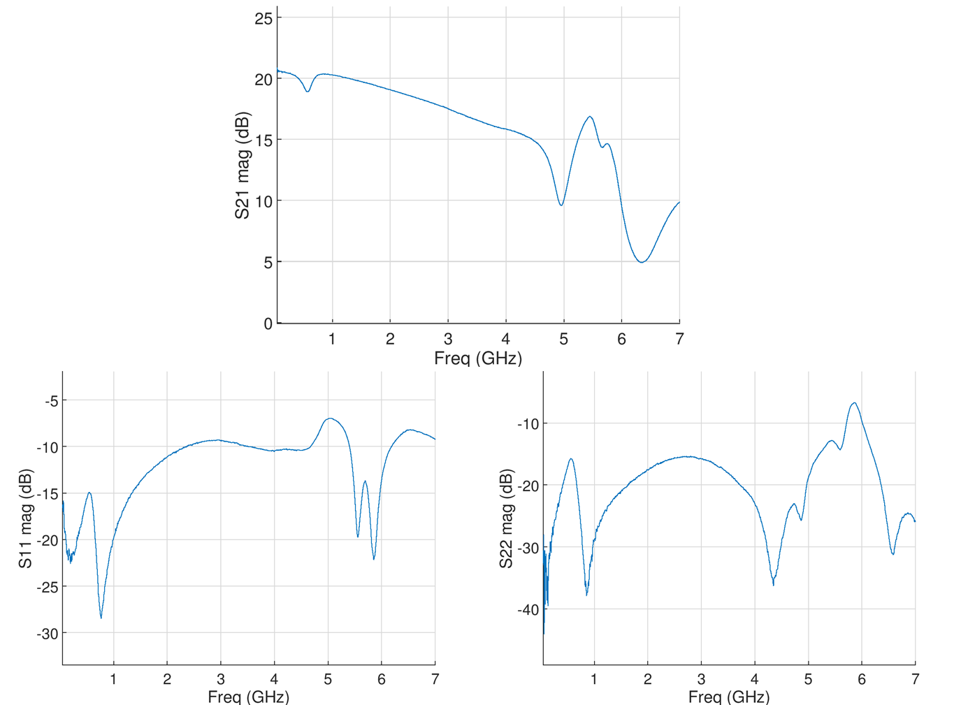
Case 2: Low-cost RF amplifier board

In this example, we will examine the performance of a low-cost RF amplifier procured from eBay. Many parts sold online from non-reputable sources may not behave according to expectations. Echoic can help you validate the performance of these components before you insert them into your costly RF setup.
The S-parameters measured in our lab reveal >20dB gain at low frequency. However, the gain is not flat and declines as a function of frequency. This indicates that this amplifier has not been designed for flat gain and may simply be a single transistor amplifier.
Case 3: Vivaldi ultra-wideband antenna input matching
Antenna design and matching is vital to wireless systems. Often antennas are procured without any way for the end-user to validate its performance. At Echoic, we can measure the input matching of antennas up to 26.5GHz.
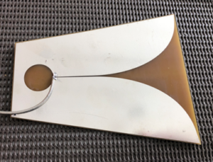
Here, we measure the S11 input match of an ultra-wideband Vivaldi (tapered slot) antenna. The nominal bandwidth is specified from 1.5GHz to 15GHz. The actual bandwidth based on measured data shows S11 < -10dB for ~ 2-16GHz. However, there is a VSWR peak around 12 GHz which may impact performance. Without the proper RF testing, these anomalies can easily be overlooked.

Case 4: RFIC SP3T Switch
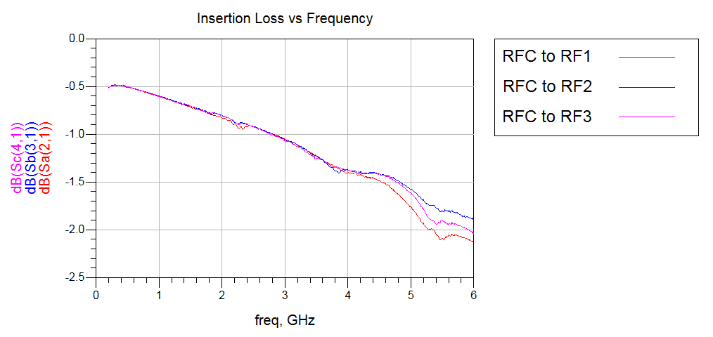
RF switches are vital in many RF systems when dealing with multi-input and multi-output transceivers or multiple antennas. Here we characterize a low-cost, high performance SP3T (single-pole, triple throw) switch, Skyworks SKY13317-373LF. According to the manufacturer, this switch operates up to 6GHz which covers WLAN, Bluetooth and ZigBee frequencies.
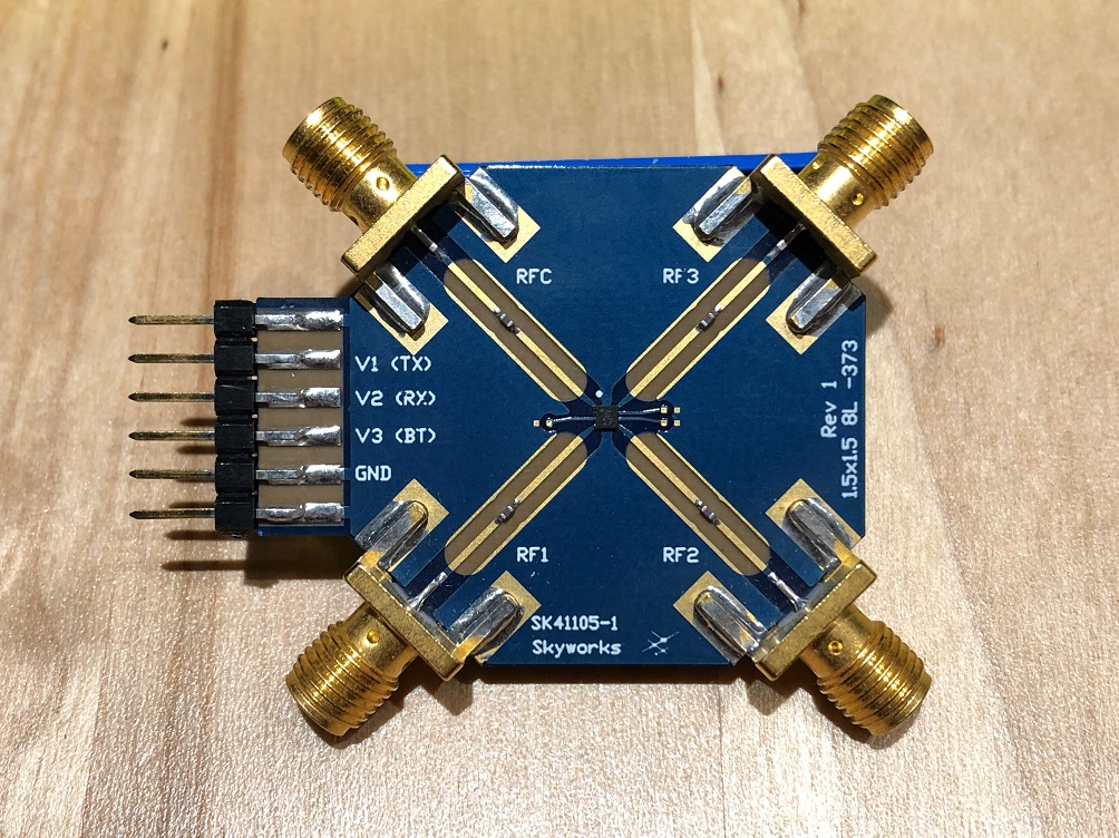
The critical design parameters of this device are the return loss, insertion loss as well as isolation between ports. Careful characterization and de-embedding of the evaluation board (fixture) is vital in obtaining precision measurements. This ensures predictable operation when the chip is implemented on a high density PCB.


Large signal power testing (Pin vs Pout, CW and pulsed)
Echoic specializes in calibrated, high power, RF and microwave testing. Presently our capabilities extend to 26.5GHz and we are able to measure amplifiers under CW and pulsed conditions. Large-signal testing enables the accurate characterization of high power GaN transistors as well as the development of high-efficiency, power amplifiers. We are equipped to measure output power (Pout), gain, efficiency (PAE and drain efficiency), case temperature as well as single-tone harmonics.
Case 5: Cernex K-band Wideband Power Amplifier
When we first obtained this amplifier, the label had been removed and we could not find the datasheet. Therefore, we had to be extremely careful in testing this amplifier. We knew that it had a gain response in the K-band, however the actual gain and output power parameters were unknown.

Through careful testing, we were able to characterize it’s bandwidth, gain and output power behavior. First, tightly controlled, power-leveled S-parameters were taken. As a nonlinear device, differences in gain over frequency can affect the gain response. Therefore, it is important to ensure leveled power across band. The S21 response for VCC=12V and ICC=2.81A is shown below.
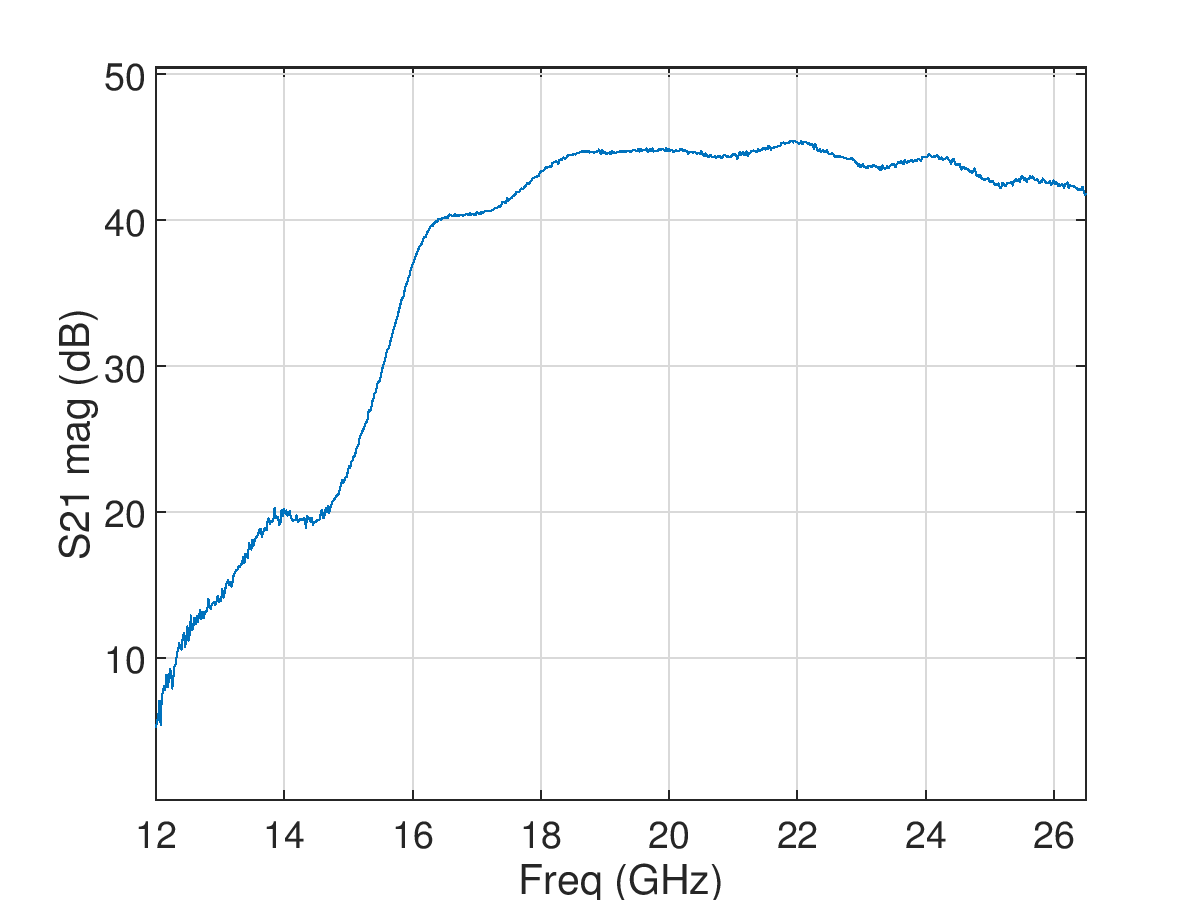
Based on the S-parametes of the device, the PA has significant gain of S21 > 40dB from 16.5GHz to 26.5GHz. This PA appears to have been designed for K-band operation
Next, we look at the output power characteristics of this PA on our precision nonlinear CW PA test band. A center frequency of 24GHz has been selected for this test.

The Cernex PA can provide Pout > 26dBm at 24GHz. For this test, we did not push the Cernex PA any higher in order to prevent damage of this expensive unit. Therefore P1dB is not observed in this plot. However 26dBm is sufficient as a driver amplifier for specific band PA testing.
Transistor IV characterization (current-vs-voltage)
Design of high efficiency power amplifiers is rooted in the IV characteristics of the core active device. RF power devices like GaN HEMT produce high power output from a small package (high power density). This results in an effect called “self-heating” which substantially degrades the IV performance of the device. Conventional methods of measuring static IV produce characteristics which are non-indicative of its IV behavior under RF excitation. Therefore current and voltage waveform shaping for switched-mode power amplifier design under static IV characteristics is invalid.
The solution for this is to employ dynamic IV characterization which utilizes short-duration voltage pulses to excite the transistor. Proper execution of this technique allows for IV characterization under controlled thermal and electrical operating points. This is the primary step for building a functionally accurate electro-thermal model.
Echoic Engineering can provide the expertise in pulsed IV characterization and modeling of GaN devices.
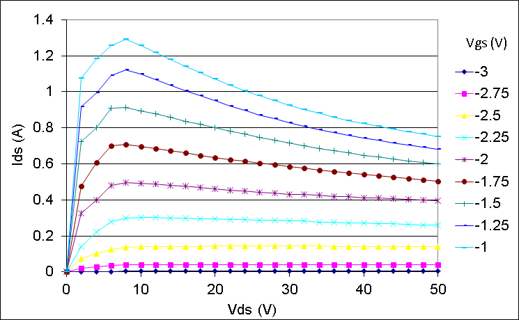
Case 6: Wolfspeed CGH40010 GaN HEMT Transistor
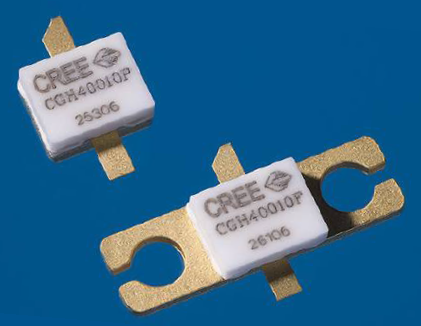
The Wolfspeed (Cree) CGH40010 GaN HEMT 10W RF Power transistor was one of the first commercially available GaN devices released and it remains in production today. The CGH40010 served as a vehicle to develop extensive characterization, modeling and design techniques which forms the foundation of our GaN circuit design service. Since its release, we have garnished extensive experience in GaN circuits ranging from 10W-200W output power and from 1.5GHz to 18GHz.
The static IV characteristics for the CGH40010 clearly show extensive self-heating which results in significant IV current droop. Clearly, these IV characteristics will be difficult to apply in conventional PA design.